| Page : | [ 1 ] | [ 2 ] | [ 3 ] | [ 4 ] | [ 5 ] | [ 6 ] |
For some time I've been meaning to play with nixie tubes. Recently I decided to do it and went out and bought a bunch of stuff to get going with it.
There's a LOT of people that have used these in various projects (mostly clocks it seems) so there's a vast amount of information out there online.
This is pretty lengthy due to me inserting a lot of images of the process. To skip to a particular page you can click a link otherwise just keep reading:
- Etching, tinning and solder mask of display board
- Etching, tinning and solder mask of driver board
- Finished and cut boards before drilling and soldering
- Boards after drilling and soldering
- Testing module and some basic code
I came across this project on Instructables.com and liked the approach he had of just "chaining" modules together with a shift register and a couple driver chips on each module.. I took his schematic and drew it into Eagle and designed the circuit boards for them (same approach as the project on instructables). There's a couple eagle part libraries out there for Nixie tubes but the part for IN-12 nixies seems to be broken so I just modified those and used them.
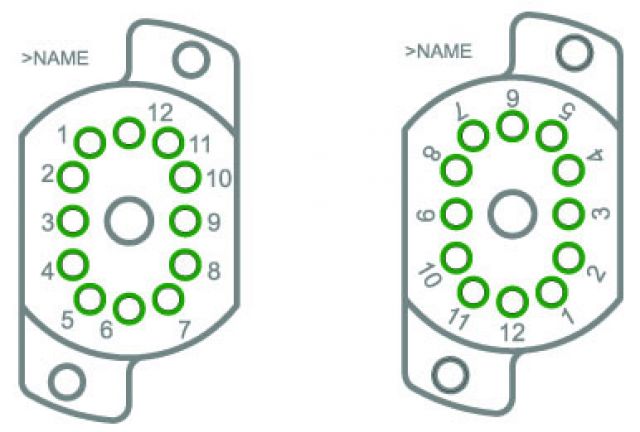
The "broken" one is on the left. The numbering is OK here if you put the Anode in at numer 1 as expected. However in actuality the pads themselves are numbered 1 through 12 starting where they have "5" and going clockwise. This implies they numbered it when looking at a tube from the bottom. That's why some people online mention getting some boards fabricated only to find out the stencil for the socket is on the top of the board but they have to insert the tube from the bottom of the board. I fixed this up in the image on the right. I have numbered the part as if looking from the top of the tube or the top of the socket and also naming the pads the same. I should add that I am appreciative to whoever drew the part up in Eagle in the first place! :)
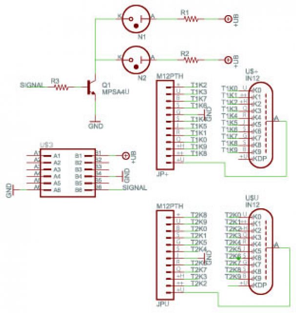
I also added a couple IN-6 nixies to the schematic for the colon markers that will be between the Hours and Minutes of the clock.
Here's the schematics for tube board:
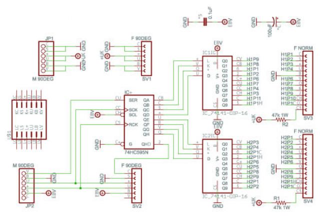
Here's the schematic for the driver board:
On the next few pages are just a bunch of images of the two boards through the process of making them and then on the last page is a couple pics of it working and some example code for running the display. Click for next page..
| (Page 1 of 6) | ||