| Page : | [ 1 ] | [ 2 ] | [ 3 ] |
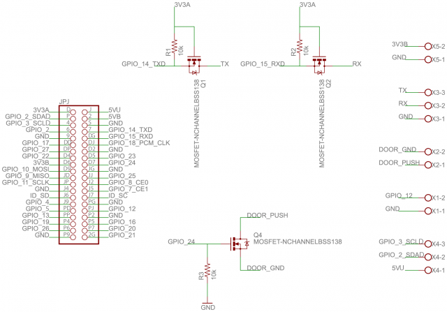
I should confess that I actually drew this schematic, etched a board and soldered all the parts with the (now crazy) notion of using one of those cheap SPI interfaced card readers. Thankfully I could just repurpose the terminals I intended to use for RX and TX to a microcontroller to now be used for D0 and D1 from the Wiegand card reader. Theres also a terminal going to a GPIO pin to send a signal to a relay for the power to the the electric door strike. There's some other unused terminals/pins that I intended for things like I2C if, for example, I wanted to add an LCD to it. Other than that the board consists simply of 2x20 header pins that plugged directly to a Raspberry Pi (ver 2 Model B) via a ribbon cable, some components for level shifting D0 and D1 and some screw terminals. The whole thing was made big enough to mount the Pi on so it was all nice and neat when deploying.
Heres some pics of the front and back of the board while testing. Try not to look at how i did NOT interlock the terminal blocks :)
Front:
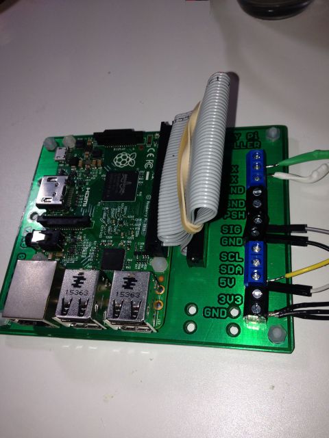
Back: (love those 90 degree traces!)

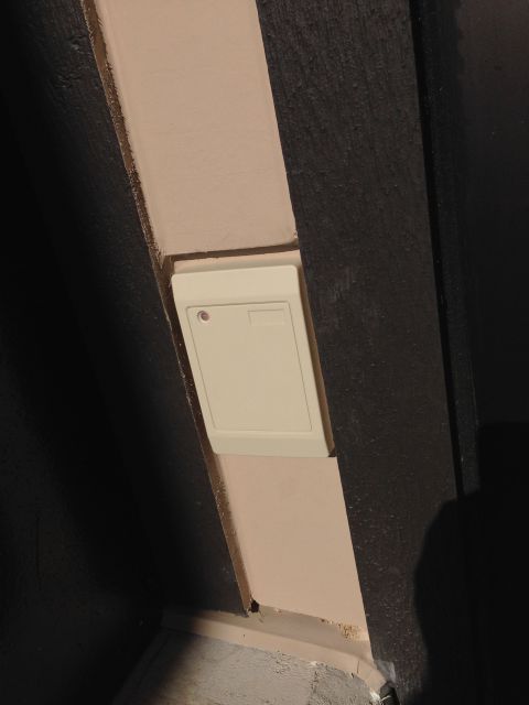
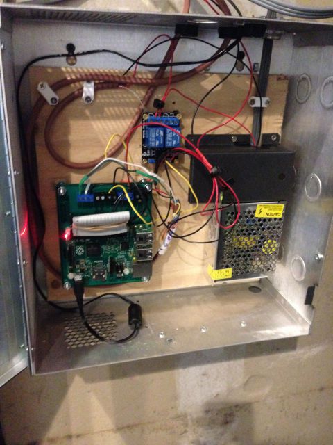
Pretty straight forward deployment. The Wiegand reader outside the building and the Pi in a box in the electrical closet. Yes, there's one of those ubiquitous, under a dollar, Chinese relay boards in there too for the door strike :)
On the wall:
In the closet:
The next page talks a bit about the software running on the Pi.
| (Page 2 of 3) | ||